a good morning for more thermal imaging

Front 2 Jan 2015

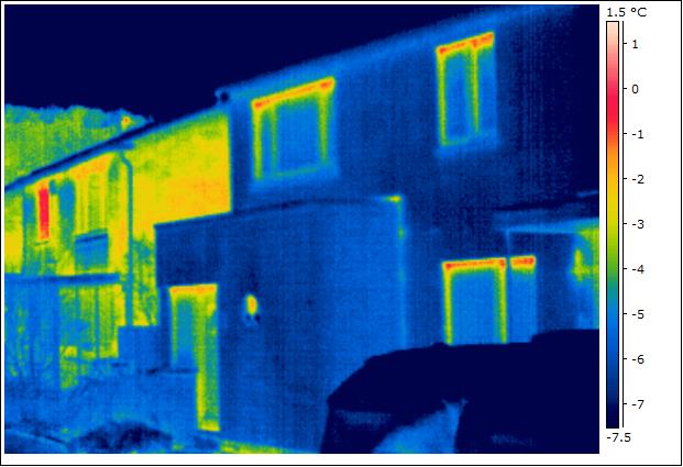
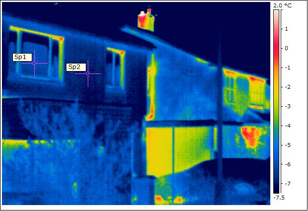
Perfect conditions this morning for some more thermal images. The house is still performing well, and as these images show, there is quite a contrasting heat loss between us and neighbouring properties (which have cavity wall insulation). The temperatures across the front elevation show good uniformity, and the triple-glazed windows are approximately the same temperature at centre pane point (spot temperatures on image below: Sp1 = minus 6.5°C and Sp2 = minus 6.2°C). As highlighted in the the posting for last year’s survey, there is some thermal bridging around the top of the windows, but budget restrictions meant that we didn’t invest in the best thermal performers. Still quite pleased with with their overall performance.

Front 1 Jan 2015

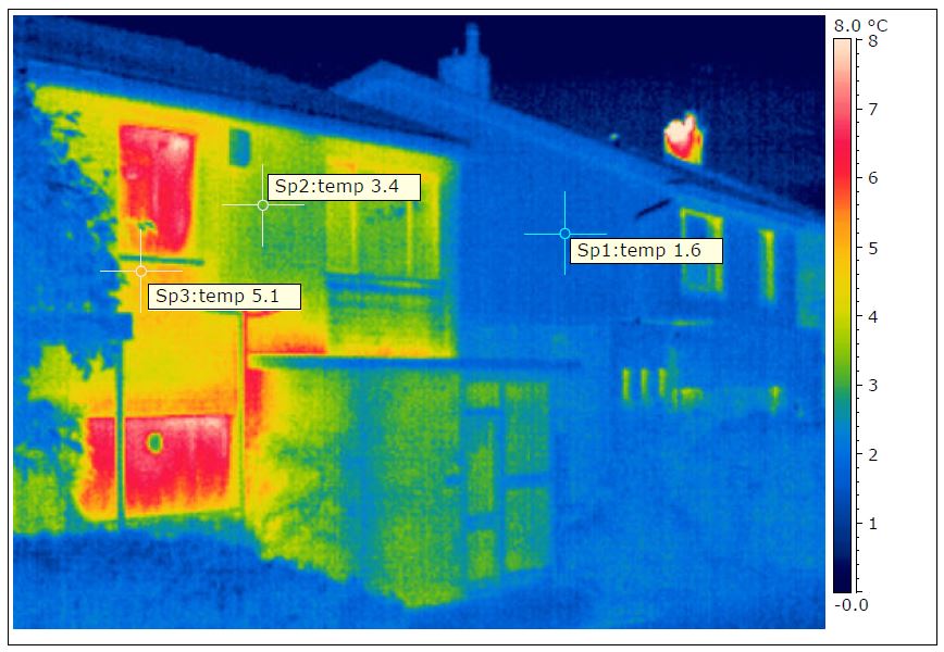
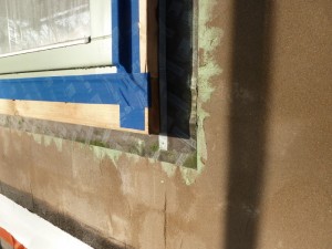
It’s not all good news however. Around the back, some problems are coming to light (in the IR spectrum). This is where the first lot of external wall insulation was applied, and it looks like we have some thermal bypass – possibly air gaps beneath the first insulation layer.

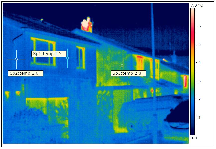
Temperatures on the spots below are: Sp1 = minus 5.0°C, Sp2 = minus 2.1°C, Sp3 – minus 2.8°CRear Flank Wall

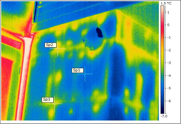
Temperatures on the spots below are: Sp1 = minus 5.0°C, Sp2 = minus 3.4°C, Sp3 – minus 2.0°C, Sp4 = minus 2.7°C, Sp5 = minus 5.0°CRear Flank Wall Low

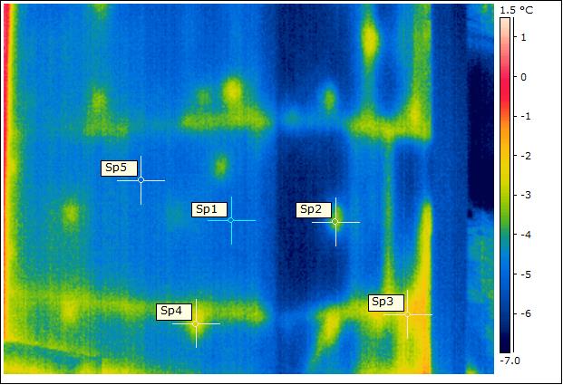
There’s not a lot we can do about this, unless a problem arises in the future. The internal scan showed good uniformity, and checks with a moisture meter do not suggest anything sinister. Not sure why this didn’t show up on last years survey – perhaps some de-lamination has occurred over the last year? It was the wettest point, I recall, so may be the adhesive has de-bonded – this is why mechanical fixings are also required. I will, at some point, do in-situ U-value measurements. If I apply heat flux plates around here then I can compare with a ‘good’ section and see what the difference is. When I know more, I’ll post. As always, I welcome comments.

fabric performance – thermography

front LHS2 IR

The fist thermal images of the finished house were taken very early in the morning at the end of January. The results are very encouraging and show, as expected, that the insulation measures are working well, and that we have significantly reduced the amount of thermal bridges, particularly for the concrete gutters. The image above shows our house in the foreground with our neighbours’ houses beyond. The temperatures of the outside of our house are the same as unheated surroundings: vehicles, plants, etc. Compared to neighbouring houses, not only are the surfaces cooler (less heat escaping), but the temperatures are more uniform, showing good insulation continuity.

front LHS IR

The image above was taken further up the street, with our house now in the background. Our neighbour’s house in the foreground has the same thermal properties as our house did when we moved in, i.e. no cavity wall insulation. The difference is quite striking between our properties.

rear IR

From the rear, the house appears to be performing well too. The wall insulation is continuous and the thermal bridging relating to the concrete gutters (as shown in an earlier post) have been eliminated. There is a small amount of thermal bridging around the new window frames, but this is expected given that we opted for less expensive windows that do not have thermal breaks in the core of the frame.

rear neighbour IR

By contrast, our neighbour’s house is losing more heat, as shown in the image above. The thermal bridges from the concrete gutters and the single leaf masonry panel beneath the windows are quite evident.

wemico trays

We have introduced some bridges that we hadn’t thought about. Ironically, it is from the steel trays that carry the external wall insulation panels that are conducting heat. These are fixed to the masonry (warm side of the insulation) and some of this heat is clearly coming through. Perhaps plastic trays would have been better. In the grand scheme of things, this is relatively minor stuff.

reader’s request: more information on window fitting

I received a request for further information about how we fitted the windows to minimise thermal bridges. So here goes:

Window fitting stage 1

Each window unit has been fitted into an external structural timber frame, or sub-frame. The sub-frame is standard C16 grade timber and doesn’t need to be tanalised as it shouldn’t become wet within the insulation layer. The size of the timbers in this case were chosen to be 60mm deep for reasons outlined below. The first timber fitted is the sill piece to act as a ledger to support the window during positioning and alignment. The window unit is fixed back to the masonry using nail plates, but most of the weight of the window is on this ledger, so it must be a good fix. The other three sides of the sub-frame can then be fitted snugly around the window:

Window fitting stage 2 Window fitting stage 3

In our case, the surrounding masonry was treated with a slurry (sand/cement) render base coat, to act as the primary air barrier. So, once the windows were fitted and the render had dried, we could deal with the airtightness sealing – sealing the window to the sub-frame and the sub-frame to the wall, using proprietary air sealing tapes. In hindsight we made an minor error here. We should have taped the sub-frame to the masonry and then rendered over the top of the render layer tape (black tape).

We chose 60mm deep sub-frame because we were using 2 x 60mm layers of insulation. The thickness of the window frame is 78mm. So the idea was to have the first layer of insulation run into the side of the sub-frame and the second layer would fly across the face of the window frame by around 40mm as shown:

window detail

Again, with hindsight, we should have used sightly deeper timber for the sub-frame (say 70-75mm) to account for the 10-15mm adhesive layer for the first insulation sheet. This would have saved a bit of  ‘shaving’ on the second layer, which, of course is a slight thermal compromise too.

The picture below shows the first layer of insulation running into the sub-frame.

window insulation

I believe the principle we have adopted is one of the best ways of minimising thermal bridges between the window frame and the surrounding masonry. We could have gone one step further and used a structural insulation material for the sub-frame, such as CompaCFoam, manufactured in Austria, but I was put off a bit by the costs (around 10x cost of timber), and, as we haven’t gone for ultra-high spec, thermal break window frames (£££), I didn’t think it was a worthwhile investment in this case (investment greater than energy saving). But, it’s worth a look.

Hope this helps and would be interested to hear if others have adopted a different approach.

week 26: balcony taking shape

balcony and support posts   balcony construction

The construction of the balcony is well under way. The design is for a ground supported type, rather than a cantilever that we thought we might have. But we have managed to limit to three support columns, which is fine – a feature perhaps. Balconies are a real problem when it comes to thermal bridging. There are a number of proprietary thermal break products that you can now get for cantilever balconies providing the deck is steel, or concrete. But for a little timber addition to our extension roof, it was proving a little over-complicated to do a cantilever option, whilst at the same time not over-compromising the thermal integrity of the building.

The ground supported solution is an independent structure, but still compromises the thermal envelope slightly as it needs to be brace back to the building. The top left picture shows, the timber ledger used to brace to the building. This is 60mm (thick) timber, so takes the place of one layer of external wall insulation. It will still have one layer of 60mm insulation over the top. However, this increases the U-value in the area of the ledger brace from 0.14 W/m².k (for the rest of the extension walls) to 0.19 W/m².k. This is fairly minor overall, and would be worried if we were after EnerPHit certification – but we’re not. Interested if anyone else has had similar dilemmas?

week 18: new window installation begins

Living room window removed  Bedroom window removed

At last, the new triple-glazed windows are being fitted. The old windows are removed, temporarily exposing the house to the elements. A timber frame surround is constructed around the structural opening as we are moving the new windows forward of the existing elevation. This is to allow them to be installed within the external insulation layer, thereby reducing thermal bridges.

Bedroom window fitting  window detail

The windows are fixed into the new surrounds and then taped to form the air seal using Tescon tape. The timber surround is taped to the masonry wall using Contega EXO tape and Orcon F sealant. However, because a lot of this work has happened in between wet and cold weather, adhesion has not been optimum. We have therefore taken the additional precaution of applying a second render base coat on top of the Contega tape.

week 16: concrete gutters removed

At last! The gutters that have been causing the leaks in our house, via the cavity of the wall (see earlier post), have been removed. These took some grinding – three cuts needed to get them off and flush with the wall (see orange elements in drawing below). The plan now is to extend the rafters such that the roof overhangs the new external wall insulation and so that we can fit a conventional gutter system.

In addition to them having failed, these concrete gutters were one of the most significant thermal bridges in the house. As shown in the drawing below, we are planning to wrap external wall insulation across the top of the roof and link it to the loft insulation layer. This will significantly reduce the thermal bridging from the remaining elements of the concrete gutter system.

week 13: other odd jobs


The rear windows to the garage and original dining room store have been removed in blocked up. The dining room store was outside of the thermal envelope of the house, completely uninsulated floor, roof and walls – a real cold spot. The final house will not be short of storage space, but we decided that it would be useful to have some utility storage accessed from the garage. This decision also helps with awkward thermal detailing – i.e. we don’t need to incorporate the store within our thermal envelope. That said, and having just noticed on the photo as I am posting this, I realise that we haven’t incorporated the external wall insulation between this block infil and the existing house walls. A thermal bridge to deal with – any ideas? Ruairi?

week 9 and 10: preparation for the slab


With the excavation and underpinning complete, focus turns to the lower ground floor slab.The graded hardcore sub-base is spread out and compacted. Along the edge of the retaining wall, we have introduced a 300 wide x 100mm deep layer of insulation to reduce the thermal bridge at the edge of the slab. I thought it would be quite a struggle to install this detail (shown in yellow on the drawing), as the top of the hardcore has to be compacted perfectly level with the top of the insulant. But the guys manage a precision installation. Given this insulation layer is beneath a structural element, we have had to make sure that we use a product with good compression strength. We could not get our specified insulation in time, so we substitute for Styrofoam Floormate 350 which has an almost identical thermal and compression performance.

A layer of sand blinding is spread out over the compacted hardcore to protect the damp proof membrane from puncture damage. We live in a medium-risk Radon area and so our membrane needs to be both moisture and gas proof. The red (depicting gas resistant) membrane goes in and a lot of care is taken ensuring that all the joints are lapped and taped sufficiently and that penetrations for the column and soil pipes are sealed around and to the membrane.

Finally, the reinforcement bars and mesh are installed in the vicinity of the retaining wall (note the protective ends installed on the mesh to reduce the risk of damage to the DPM) and the form-work completed ready for the concrete pour.

how much calculation and modelling?

On of our departures from the Passivhaus, or EnerPHit standard is that we do not plan to spend time doing numerical energy models, such as PHPP, which would be needed for certification. Our only thermal calculations to date have been for thermal bridge analysis, known as Ψ-values, and U-values for determining the thickness and extent of insulation to be used for our walls, floors and roofs, junctions, etc. Our scope is limited by the existing structure and there are elements of work that are not justifiable right now. For example, our roof junctions are a weak thermal point, but the roof is in sound condition. It does not make any economical sense to take it off solely to improve its thermal performance at the eaves and verge. In the time that we plan to live here, there may be a ‘blue moon’ opportunity when we do need to do some major work on the roof and the comparative cost of dealing with the thermal weak points will be <10% of the roof work costs.