week 17 and 18: existing roof extended

rafter extension

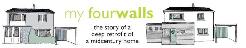
The rafters to the existing pitched roof have been extended now that the concrete gutters have been removed. This will allow the roof to extend sufficiently in front of the external wall insulation. The Intello air barrier membrane beneath the rafters is Tescon taped to the existing timber wall plate to reduce the air leakage out of the cavity head (see drawing in previous post).

rafter insulation

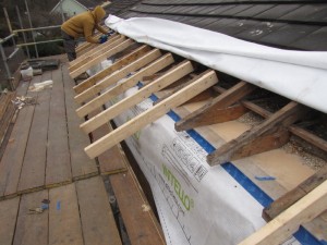
We are also insulating between the rafters to provide insulation continuity between the external wall insulation and the loft insulation. The rigid insulation panels are squeezed tightly between the timbers and extend approx 0.5m above the (future) loft insulation. This means that they should also serve to provide a ventilation channel into the loft. This ventilation is necessary to remove any condensation from the cold loft space, and is often provided via proprietary ventilation channels.

New, matching roof tiles have been sourced. These will soon be fitted along with the new fascia and gutters – to be continued.

week 17 and 18: base render coat

Extension wall slurry coat  Existing wall slurry coat

The base render, or slurry coat to the existing walls and extension walls has now commenced. As well as providing a smooth substrate for the external wall insulation, this render coat also serves as our primary air barrier, highighted in blue in the section below.

wall section

Working between sub-zero temperatures (before Christmas) and the rain, the rendering is still ongoing, but having done the front of the property, our house is starting to take on a different look…

house metamorphosing

week 15: breakthrough preparations


The structural steel for the breakthrough to the extension from the existing hall was put in this week. The opening will be 2m wide, enough for access to the stairs down to the lower ground floor and to get to the studio on the ground floor.

With the cold weather now setting in, we decide that it is best to leave the masonry in place beneath the steel. We will need to remove at least the outer leaf shortly in order to close off the cavity prior to injecting the cavity wall insulation.

week 5: underpinning starts

After the slab is removed and the earth excavated to the right level, the underpinning of the walls can commence. The photo above shows the first corner section of underpinning complete. Each section is approximately 1200mm long and is cast in alternate sequences. The photo shows the form-work for the second section being removed, the third and fourth sections (either side of the second) can be cast in one sequence, as per the structural engineer’s details.

The underpinning will continue along the internal side wall (behind the column in the photo) and progressively along the external side wall (far right in photo) in tandem with the excavation along the wall. Let’s hope for good weather!


week 5: out comes the lower ground floor

The picture shows the extent of the steel work now that the scaffolding has been removed. Toward the base of the new steel column, you can just make out the thermal break. The new insulated floor level is approximately 30mm above this break, and so the existing needs to come out.

Concerned that a breaker drill will cause too much vibration (and noise), it is decided that a concrete saw would be best. This will cut the slab into chunks of manageable size for the digger to ‘scoop out’.

The photo above shows the saw in use. It takes best part of the day to cut the slab, but it is a success and the slab is removed. Beneath the slab is solid, rocky, undisturbed ground. The digger scoops out around 650mm of earth beneath the slab. This reveals the base of the back and side walls, ready for the under pinning. See next update

week 4: safely aground

Well, first of all the base for the column needs to be prepared. Digging down around 1 metre below the existing ground slab and cutting through the existing and substantial foundations.

This new base will take the load of the whole corner of the house and needs to be pretty substantial. Our structural engineer specifies a depth of 400mm, but we decide to take it deeper to almost 600mm to get below the level of the existing foundations.

And so once the base is cast, the new post arrive s(late again!). The picture above shows it sitting on the new concrete base, which has been drilled and injected with the chemical resin anchor (as used for the horizontal steels).

The picture also shows the thermal break used in the column. This reduces the thermal conductivity in the column by a factor of 1500 compared to having no thermal break. The steel column has a thermal conductivity of 54 W/m.k, whereas the break has a conductivity of 0.035 W/m.k, This is a critical element for limiting the thermal bridging through the structure. It is still a compromise: ideally we wouldn’t be penetrating the thermal envelope with structural elements, but where this is necessary, so are these thermal de-couplers.

Finally, the column base is shuttered and then grouted with structural grout (as shown in the photo above). It will be bolted on Monday and the Acros will be struck. A project milestone and time for a quick glass of bubbly stuff before the guys go home for the weekend. They’ve done me proud, and I can relax a little having some proper structure beneath us again!

week 3: we’re afloat!

In addition to the Acros and Strongboys, a further steel ‘needle’ was inserted to the external corner and another steel placed beneath the slab to spread the point load. After a few more checks and tightening up of the supports, the concrete lintel beneath the slab was cut out and the side wall partially demolished, exposing the edge of the slab in readiness for the steels.

The picture below, taken a little earlier in the week, shows the side wall slab in good condition:

The same can’t be said for the rear part of the slab, which has softened from water and salt damage over the years. As the picture below shows, part of the slab edge has broken away:

As we are relying on this edge (structurally: the slab sits into the web of the steel), we need to strengthen it using Sika Armocrete repair mortar. As a further precautionary measure, the bottom flange of the steel will be extended by 100mm to make sure it reaches sound concrete beyond the edge.


week 3: ‘strongboys’ ready!

Scaffolding went up on Tuesday followed by the installation of an array of Strongboy supports and Acro props in preparation for the demolition of the side wall and removal of the concrete lintel at the rear, which supports the slab above the former loggia.

The picture above shows the matrix of Acro supports. The concrete lintel being removed (with white render coat) is just visible at the top right of the picture.

Now ready for some serious demolition!

week 2: structural alteration beneath the house

There is a vast void beneath the house, thanks to the slope that the house is built on. In its present state, it cannot be effectively used due to the amount of structural walls and supports. Some of these are now being demolished and replaced with lintels on block piers. The photo above shows the block piers constructed on top of the existing retaining wall. Elsewhere, access hatches are being cut into the walls as can be seen in the photo below.

Opening up under the house in this way allows the space to be used more effectively. The part of the void in the photos (with the greatest headroom) will be part of the heated volume of the house and will become a plant room for the hot water cylinder and an archive/storage area to house items currently in the loft. The loft will be almost unusable for storage due to the amount of insulation proposed and its low (22°) pitch.

The void will also enable good access for installing the new services: pipes, cables, ducts, and will be excellent for getting the floor insulation into the unheated part of the void toward the front of the house where it becomes more of a crawl space. The drawing extract below shows the extent of the void and the delineation between heated and unheated areas (insulation and air barrier line shown in green).

week 2: structural alterations

In meeting the structural engineer, it was agreed that the lower ground slab should stay for the time being as it will be easier to temporarily prop the upper slab from this. In the meantime we have been deciding the best approach for the main structural alterations and the insertion of the steels.

First of, five of the seven side windows have been in-filled, the remaining two will come out later. In-filling the windows will strengthen the wall prior to the demolition of the lower section of this wall.


Exposing the slab edge reveals that it is supported entirely by the inner brick leaf. This makes the sequencing simpler as the slab can be supported as proposed, with an array of Acro supports below. The outer brick leaf will need supporting independently, but there is not as much load to contend with as we thought. As the sketch detail above right shows, we have a slight clash with the proposed steel now and we will need to trim the top flange such that it doesn’t foul the inner brick leaf. Our structural engineer is okay with this providing we bolt the web of the steel to the edge of the concrete slab.