backblog #1: loft insulation

I have been neglecting this blog and now have a backlog of stuff to update. So, resuming with the loft insulation (and ventilation ducts in the loft)…

Skip full of itchy stuff empty loft

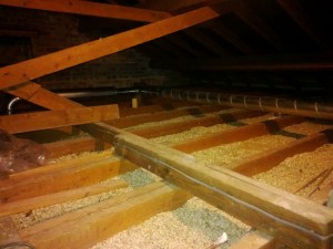
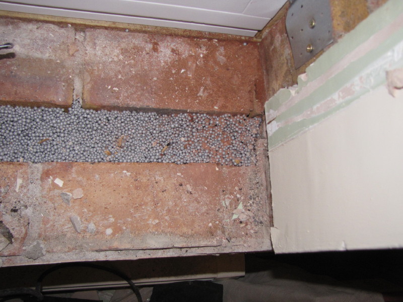
The old glass fibre insulation was stripped out of the loft (lovely job), leaving only the original (pathetically thin) layer of granulated vermiculite insulation. I couldn’t see the point of removing this, so it was left in place. Once cleared and cleaned, the loft was ready for the MVHR duct installation.

Supply and extract risers boxings

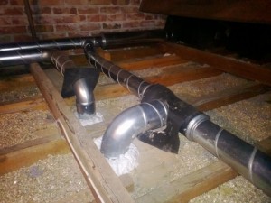
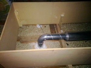
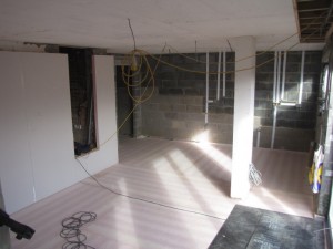
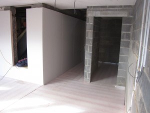
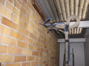
The Lindab SAFE ducting is installed approx 200mm above the ceiling (100mm joist + 100mm tie beam). This puts the top of the 100mm ducts approximately at the top of the proposed insulation layer. As these ducts form part of the insulated envelope, I feel it is necessary to create MDF boxings, or shutters around the ducting to allow the insulation to envelop the ducts completely: 300mm to the sides and above, giving some 600mm of insulation to the loft in these areas. The photo above right shows an example of the boxings prior to the insulation.

Warmcel stack  blowing machine

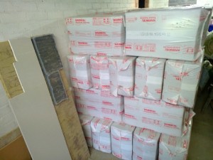
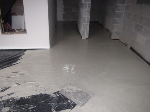
We have used Warmcel for our loft insulation. This is 100% cellulose (recycled newspaper). A total of 85 bags have been installed using a blowing machine.

Warmcel installation

Finished insulation

The photo above shows the finished insulation, in and around the ventilation duct boxings. The boxings account for just over a third of the loft floor area and therefore the area-weighted U-value for the loft is now 0.10W/m².K, compared to 0.13W/m².K if the entire loft insulation was just 300mm deep.

weeks 24 and 25: boarding out and screeding

LGF Dry lining  LGF dry lining

LGF dry lining

The internals are now starting to transform the space from being a building site. The extension area at both the lower ground level and ground level is now being boarded out. The ceiling boarding is magnesium silicate by Multi-Pro. This is a moisture resistant board and has a greater breath-ability than plasterboard. The external walls will be plastered, but we have used 62.5mm Kingspan K17 insulated plasterboard on the internal walls (external prior to extension) that have been underpinned.

The floor insulation has also been laid. Again, we have used Kingspan K3 floorboard. This is 100mm thick, and achieves a U-value of 0.13 W/m².K. The insulation is laid directly onto the sub slab and covered with polythene ready for the screed. The screed arrived today on a mixer lorry. We are using a liquid flow screed, which allows a thinner layer (30mm) compared to traditional sand/cement screed (65mm). I’ve not used this type before, so will be interested to see how successful it is.

Tarma pre-mix lorry doing its stuff screed flowing in

week 17: cavity wall insulation

CWI injection  CWI Injection at high level

The cavity wall insulation (CWI) has now gone in. Primarily, it will be the external wall insulation that will be providing the heat loss reduction and achieving our U-values of <0.14 W.m².K. However, in order for the external insulation to be effective, we need to fill the cavity as best as possible to minimise/eliminate air currents. Otherwise, warm air entering the cavity will rise out at the cavity head to atmosphere, bypassing the external wall insulation. The picture above right shows the insulation being injected above the ceiling line of the top floor (usually installations stop just above ceiling level). This is in order to reduce air currents all the way to the cavity head.

We have selected Platinum Ecobead as the CWI insulant. These are expanded polystyrene spheres that are injected at high pressure into the cavity – the manufacturer’s claim this totally fills the cavity, which is good. It is also blown with an adhesive, which means that the beads will stay in place, and not slump, when it dries. As we are replacing the windows and sills, a few days after the CWI installation, we get a unique opportunity to look inside the cavity to see how well the Ecobead has filled it. I am impressed!

viwew of cavity at window sill

week 12: tanking and below ground insulation


Fortunately, it’s been a good, dry week to get the tanking onto the retaining wall. The below-ground (substructure) element of wall needs to continue the waterproof and gasproof characteristic of the floor. We opt for self-adhesive Visqueen Gas Resistant Tanking Membrane. The wall was first treated with a bitumen primer (above left photo) and left to dry and the tanking membrane went on the following day. It was a bit cold, so the self-adhesive element needed a bit of help with a roofer’s torch to get it to stick to the wall, but it went on finally.


The insulation goes on against the tanking. We are using Kingspan Styrozone H350R. We cannot use any mechanical fixings to attach this insulation to the wall (as it will compromise the waterproofing). I speak to Kingspan to see what adhesives they recommend, but they advised that no grab adhesives of any kind (water- or chemical-based) should be used. We therefore opted for an additional ‘sacrificial’ low-cost fibre board to hold the insulation temporarily in place and to protect the insulation during backfilling. The weight of the backfilled stone and earth, once compacted, will hold the insulation firmly in place. The photo (above right) shows a plan view of the insulation against the tanking as the hardcore backfill was going in – absolutely no air gaps between the wall and the insulation.

week 11: the superstructure emerges


It’s been a long time coming, but we are finally out of the ground with the new extension. The floor slab had cured sufficiently over the weekend, so first thing on Monday the shuttering was removed. The guys wasted no time in getting on with the retaining wall structure. We are using dense concrete hollow blocks with reinforcing rods. The hollows are then filled with a strong concrete mix. The retaining wall is approximately 2 metres high and the side (boundary) wall ‘steps’ to suit the slope of the land (see photo below taken earlier in the week). Above retaining level, the blocks change to aerated type using Celcon H+H Hi-Strength blocks. Building above the retaining wall is not scheduled until next week, but, even with pretty grotty weather, the aerated blocks go up almost to storey height.

The Celcon blocks used above ground level have a much better (lower) thermal conductivity than the dense concrete blocks used for the retaining wall. With the application of 120mm of external insulation, the walls will achieve an excellent U-Value of 0.14 W.m²K. By comparison, the retaining wall element achieves a slightly poorer 0.17 W.m²K, which is still very good. This would be higher again (0.19) if this wall type continued above ground – the retained earth, in effect, is another layer that helps to minimise the heat loss. By comparison, the current Building Regulations require the U-value for new extension walls to be no higher than 0.28 W.m²K.

week 9 and 10: preparation for the slab


With the excavation and underpinning complete, focus turns to the lower ground floor slab.The graded hardcore sub-base is spread out and compacted. Along the edge of the retaining wall, we have introduced a 300 wide x 100mm deep layer of insulation to reduce the thermal bridge at the edge of the slab. I thought it would be quite a struggle to install this detail (shown in yellow on the drawing), as the top of the hardcore has to be compacted perfectly level with the top of the insulant. But the guys manage a precision installation. Given this insulation layer is beneath a structural element, we have had to make sure that we use a product with good compression strength. We could not get our specified insulation in time, so we substitute for Styrofoam Floormate 350 which has an almost identical thermal and compression performance.

A layer of sand blinding is spread out over the compacted hardcore to protect the damp proof membrane from puncture damage. We live in a medium-risk Radon area and so our membrane needs to be both moisture and gas proof. The red (depicting gas resistant) membrane goes in and a lot of care is taken ensuring that all the joints are lapped and taped sufficiently and that penetrations for the column and soil pipes are sealed around and to the membrane.

Finally, the reinforcement bars and mesh are installed in the vicinity of the retaining wall (note the protective ends installed on the mesh to reduce the risk of damage to the DPM) and the form-work completed ready for the concrete pour.