Indoor Air Quality: VOCs

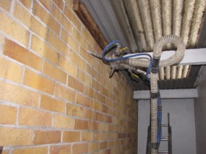
This first article on the topic of IAQ reports on the results from enhanced monitoring and air sampling, which took place during the winter (2015/16) to evaluate the levels of volatile organic compound (VOCs) pollutants inside the home, and the potential increase of these pollutants when the ventilation rate was reduced.

The chart shows the results of samples taken from the main bedroom and living room over two 7-day periods. The first set of samples were taken with the MVHR ventilation running continuously (i.e. as normal) delivering 220 m³/hour (approximately 0.5 air changes). The second set of samples were taken with the ventilation set to unoccupied mode, which delivers 140 m³/hour for 15 minutes in every hour (less than 0.1 air changes) – show as ‘ventilation off’ on the chart. Activities and occupancy were similar, and there was a two-week interval between the samples being taken.

According to the performance criteria in Approved Document F, exposure to TVOCs should not exceed 300 μg/m³ averaged over an 8-hour period. It is clearly evident that, whilst the ventilation is running normally, both the living room and main bedroom fall well within this threshold value, measuring 80 and 90 μg/m³ respectively, averaged over the 7-days. However, the repeat measurement with the reduced ventilation rate shows and increase to 340 and 370 μg/m³ receptively for these rooms – an increase of around 75%. The ventilation rate was reduced at the beginning of the sampling, so the observed concentration would likely be higher still if the sampling commenced at a later point.

Whilst TVOCs do not give an indication of the ‘toxicity’ of the air, analysis of the chromatograms identified chemicals, which included: 2-chloropropane – a chemical used as a blowing agent in some phenolic insulants; α-pinene and 3-carene – naturally occurring, derived from oils in woods, but still can cause skin irritation at higher concentrations; texanol – a solvent used in paints. In the lower ventilation (2nd) sample the same chemicals were observed, but at higher concentrations.

This experiment demonstrates the importance in the use of purpose-provided ventilation. Without ventilation, and within an airtight property, the concentration levels of pollutants inside seem set to rise – who knows how high these concentrations would have risen to if the experiment continued for longer than 7 days.

More IAQ stuff to come.

reader’s request: more information on window fitting

I received a request for further information about how we fitted the windows to minimise thermal bridges. So here goes:

Window fitting stage 1

Each window unit has been fitted into an external structural timber frame, or sub-frame. The sub-frame is standard C16 grade timber and doesn’t need to be tanalised as it shouldn’t become wet within the insulation layer. The size of the timbers in this case were chosen to be 60mm deep for reasons outlined below. The first timber fitted is the sill piece to act as a ledger to support the window during positioning and alignment. The window unit is fixed back to the masonry using nail plates, but most of the weight of the window is on this ledger, so it must be a good fix. The other three sides of the sub-frame can then be fitted snugly around the window:

Window fitting stage 2 Window fitting stage 3

In our case, the surrounding masonry was treated with a slurry (sand/cement) render base coat, to act as the primary air barrier. So, once the windows were fitted and the render had dried, we could deal with the airtightness sealing – sealing the window to the sub-frame and the sub-frame to the wall, using proprietary air sealing tapes. In hindsight we made an minor error here. We should have taped the sub-frame to the masonry and then rendered over the top of the render layer tape (black tape).

We chose 60mm deep sub-frame because we were using 2 x 60mm layers of insulation. The thickness of the window frame is 78mm. So the idea was to have the first layer of insulation run into the side of the sub-frame and the second layer would fly across the face of the window frame by around 40mm as shown:

window detail

Again, with hindsight, we should have used sightly deeper timber for the sub-frame (say 70-75mm) to account for the 10-15mm adhesive layer for the first insulation sheet. This would have saved a bit of  ‘shaving’ on the second layer, which, of course is a slight thermal compromise too.

The picture below shows the first layer of insulation running into the sub-frame.

window insulation

I believe the principle we have adopted is one of the best ways of minimising thermal bridges between the window frame and the surrounding masonry. We could have gone one step further and used a structural insulation material for the sub-frame, such as CompaCFoam, manufactured in Austria, but I was put off a bit by the costs (around 10x cost of timber), and, as we haven’t gone for ultra-high spec, thermal break window frames (£££), I didn’t think it was a worthwhile investment in this case (investment greater than energy saving). But, it’s worth a look.

Hope this helps and would be interested to hear if others have adopted a different approach.

week 26: first air leakage test

Air leakage test No.1Photo: Tom Morris

I carried out the first air leakage pre-test this week. Our target for the extension area is 1.5 m³.h/m². The primary air barrier on this project is on the outside of the masonry, i.e. just behind the external wall insulation, which will be applied shortly. So, we decide to do an initial test to see if there are underlying issues prior to covering everything up.

cable grommet flue grommet

The base render coat acts as the main air barrier, so anything coming through this must be sealed. Cables and the boiler flue are provided with grommets, providing a good seal around these penetrations. The windows have been sealed with tape (see earlier post) around the outside, but the internal sealing hasn’t been done yet.

So to the result… we get a pretty good 2.7 m³.h/m². Leakage detection identifies a significant amount of leakage around the internal openings to the existing house, which were temporarily sealed, so this needs improvement prior to the next test. There is a small amount of leakage around the windows, due mostly to the incompleteness of the inner seal, and a little through the drains (not filled with water yet). Also, our secondary air barrier, internal plaster, hasn’t been done yet. But all in all this isn’t bad, and believe we’re on track for meeting our target of 1.5 m³.h/m².

week 18: new window installation begins

Living room window removed  Bedroom window removed

At last, the new triple-glazed windows are being fitted. The old windows are removed, temporarily exposing the house to the elements. A timber frame surround is constructed around the structural opening as we are moving the new windows forward of the existing elevation. This is to allow them to be installed within the external insulation layer, thereby reducing thermal bridges.

Bedroom window fitting  window detail

The windows are fixed into the new surrounds and then taped to form the air seal using Tescon tape. The timber surround is taped to the masonry wall using Contega EXO tape and Orcon F sealant. However, because a lot of this work has happened in between wet and cold weather, adhesion has not been optimum. We have therefore taken the additional precaution of applying a second render base coat on top of the Contega tape.

week 17 and 18: base render coat

Extension wall slurry coat  Existing wall slurry coat

The base render, or slurry coat to the existing walls and extension walls has now commenced. As well as providing a smooth substrate for the external wall insulation, this render coat also serves as our primary air barrier, highighted in blue in the section below.

wall section

Working between sub-zero temperatures (before Christmas) and the rain, the rendering is still ongoing, but having done the front of the property, our house is starting to take on a different look…

house metamorphosing

week 17: cavity wall insulation

CWI injection  CWI Injection at high level

The cavity wall insulation (CWI) has now gone in. Primarily, it will be the external wall insulation that will be providing the heat loss reduction and achieving our U-values of <0.14 W.m².K. However, in order for the external insulation to be effective, we need to fill the cavity as best as possible to minimise/eliminate air currents. Otherwise, warm air entering the cavity will rise out at the cavity head to atmosphere, bypassing the external wall insulation. The picture above right shows the insulation being injected above the ceiling line of the top floor (usually installations stop just above ceiling level). This is in order to reduce air currents all the way to the cavity head.

We have selected Platinum Ecobead as the CWI insulant. These are expanded polystyrene spheres that are injected at high pressure into the cavity – the manufacturer’s claim this totally fills the cavity, which is good. It is also blown with an adhesive, which means that the beads will stay in place, and not slump, when it dries. As we are replacing the windows and sills, a few days after the CWI installation, we get a unique opportunity to look inside the cavity to see how well the Ecobead has filled it. I am impressed!

viwew of cavity at window sill

bathroom window wall (or sieve)

The toilet has come out, freeing up the remaining floor for re-boarding and the window wall for the rest of the re-plastering. Around the soil and vent pipe (shown) there were huge holes through the inner leaf brick wall, measuring approximately 350 x 150mm – a very significant air leakage path (sorry no photo). Bathrooms and kitchens are key culprit areas for air leakage, particularly over the years as trade plumber after trade plumber make alterations for new appliances, sanitaryware, etc. It is always worthwhile looking for air leakage paths and dealing with them before the new installation goes in. In this case, the hole was infilled with masonry and mortar and plastered over. Continue reading

a not very private bathroom

The first phase of floorboards are in along with the new corner vanity unit. The door needs to be relocated to suit the new bath position. The existing partition wall between bathroom and landing is demolished, ready for the new stud wall and door position. This gives further opportunities to do more air leakage sealing around the wall frame.

the shower is in

Well, the shower is in and working, but now the work continues around it. Probably not the most practical solution, but this is the reality of working in an area that needs to be kept in use. The floorboards have come up as the originals were in poor repair. Also, there was a strip in the floorboards where the original partition was. Continue reading