Don’t play with radon!

Our house, built into a slope and on a rock seam, also lies within a medium-high radon risk area, according to PHE/UKradon. A while back, I applied to UKradon for a home testing kit, which comprised three dosimeters: one for each floor. When the results came back in from the laboratory, some of my fears were confirmed. Ideally, levels should be below 100 (Bq/m³), but not exceed 200.

Our results were as follows:

  • Bedroom (top floor): 37
  • Living Room (ground floor): 85
  • Kitchen/diner: 290!

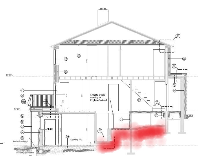
I suspected the source to be ground radon. The kitchen/diner and extension is built on a new slab with a gas-proof barrier (see earlier post). But, the undercroft beneath the original house simply has a concrete slurry cap (nominal 4in thick) poured on top of the subsoil – I believe the radon is permeating through this cap. The section below has been highlighted to show the suspected radon source (red):

Continue reading

Indoor Air Quality: VOCs

This first article on the topic of IAQ reports on the results from enhanced monitoring and air sampling, which took place during the winter (2015/16) to evaluate the levels of volatile organic compound (VOCs) pollutants inside the home, and the potential increase of these pollutants when the ventilation rate was reduced.

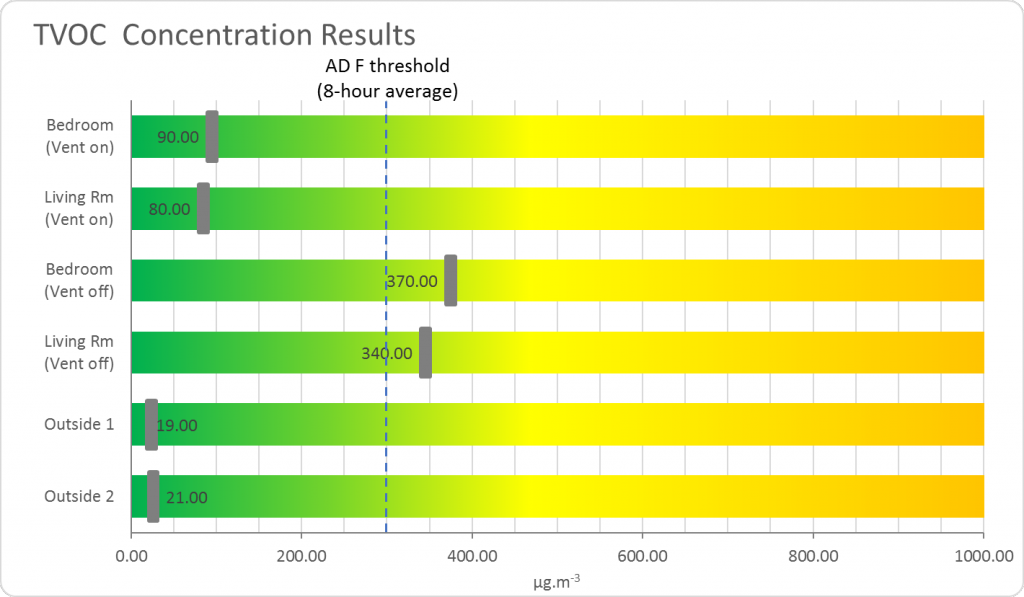
The chart shows the results of samples taken from the main bedroom and living room over two 7-day periods. The first set of samples were taken with the MVHR ventilation running continuously (i.e. as normal) delivering 220 m³/hour (approximately 0.5 air changes). The second set of samples were taken with the ventilation set to unoccupied mode, which delivers 140 m³/hour for 15 minutes in every hour (less than 0.1 air changes) – show as ‘ventilation off’ on the chart. Activities and occupancy were similar, and there was a two-week interval between the samples being taken.

According to the performance criteria in Approved Document F, exposure to TVOCs should not exceed 300 μg/m³ averaged over an 8-hour period. It is clearly evident that, whilst the ventilation is running normally, both the living room and main bedroom fall well within this threshold value, measuring 80 and 90 μg/m³ respectively, averaged over the 7-days. However, the repeat measurement with the reduced ventilation rate shows and increase to 340 and 370 μg/m³ receptively for these rooms – an increase of around 75%. The ventilation rate was reduced at the beginning of the sampling, so the observed concentration would likely be higher still if the sampling commenced at a later point.

Whilst TVOCs do not give an indication of the ‘toxicity’ of the air, analysis of the chromatograms identified chemicals, which included: 2-chloropropane – a chemical used as a blowing agent in some phenolic insulants; α-pinene and 3-carene – naturally occurring, derived from oils in woods, but still can cause skin irritation at higher concentrations; texanol – a solvent used in paints. In the lower ventilation (2nd) sample the same chemicals were observed, but at higher concentrations.

This experiment demonstrates the importance in the use of purpose-provided ventilation. Without ventilation, and within an airtight property, the concentration levels of pollutants inside seem set to rise – who knows how high these concentrations would have risen to if the experiment continued for longer than 7 days.

More IAQ stuff to come.

backblog #2: mvhr system commissioned

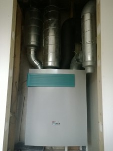
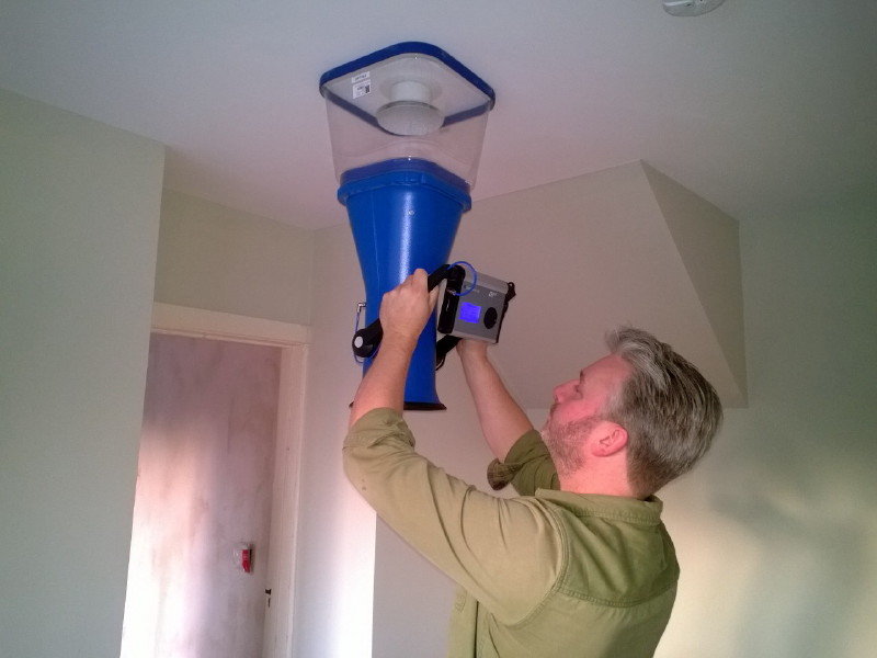
 Paul Novus300 Commissioning in progress

The heat recovery ventilation system has been running for some three months now. The system is a Paul Novus 300 unit, which has a heat recovery efficiency of up to 94%. The system commissioning included balancing the supply and extract air flows and setting the fan speeds for each setting. This all went well and the system balanced well (which isn’t always the case). The photo above left shows the ventilation unit set within a cupboard within my new office. With all the attenuators on the ductwork (see earlier post), and the sound insulation around the cupboard, the system is almost silent: audible only in boost mode.

The photo above right shows the commissioning taking place. The total air flow was measured and adjusted through the intake and exhaust terminals (outside) to ensure total design air flow was achieved. The internal terminals within each rooms are then measured, adjusted and-re-measured to ensure each room receives the right air flow.

More performance data will follow on future blog postings. Keep checking back.

backblog #1: loft insulation

I have been neglecting this blog and now have a backlog of stuff to update. So, resuming with the loft insulation (and ventilation ducts in the loft)…

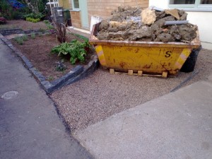
Skip full of itchy stuff empty loft

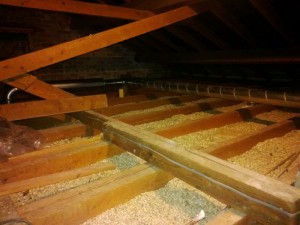
The old glass fibre insulation was stripped out of the loft (lovely job), leaving only the original (pathetically thin) layer of granulated vermiculite insulation. I couldn’t see the point of removing this, so it was left in place. Once cleared and cleaned, the loft was ready for the MVHR duct installation.

Supply and extract risers boxings

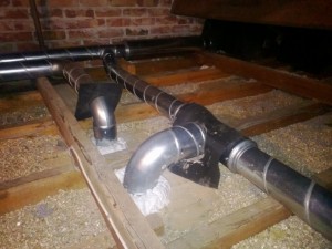
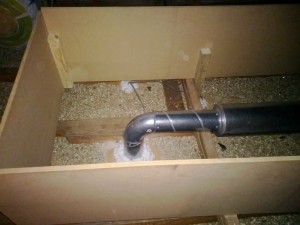
The Lindab SAFE ducting is installed approx 200mm above the ceiling (100mm joist + 100mm tie beam). This puts the top of the 100mm ducts approximately at the top of the proposed insulation layer. As these ducts form part of the insulated envelope, I feel it is necessary to create MDF boxings, or shutters around the ducting to allow the insulation to envelop the ducts completely: 300mm to the sides and above, giving some 600mm of insulation to the loft in these areas. The photo above right shows an example of the boxings prior to the insulation.

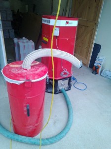
Warmcel stack  blowing machine

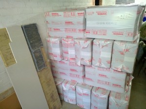
We have used Warmcel for our loft insulation. This is 100% cellulose (recycled newspaper). A total of 85 bags have been installed using a blowing machine.

Warmcel installation

Finished insulation

The photo above shows the finished insulation, in and around the ventilation duct boxings. The boxings account for just over a third of the loft floor area and therefore the area-weighted U-value for the loft is now 0.10W/m².K, compared to 0.13W/m².K if the entire loft insulation was just 300mm deep.

weeks 36 to 39: ventilation installation

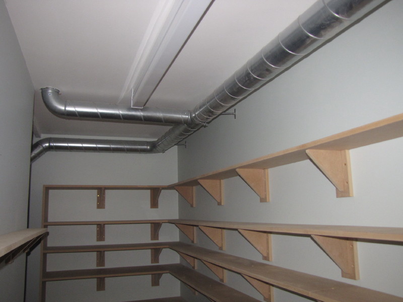
MVHR in Pantry

We are fitting a balanced mechanical ventilation system with a heat recovery unit (MVHR). This is a ducted supply and extract system that removes moist air from wet rooms and supplies fresh air to living rooms and bedrooms. The heat energy in the extract air stream is recovered by the heat recovery unit and this is channelled into the supply air stream so that the heat energy is not lost. I evaluate many of these systems as part of my work and have found that there are frequently problems with the way the systems are designed, installed, or commissioned.. Often there are shortcomings on all three elements, – and the systems are getting bad press as a result. As we are beginning to build to increasing airtightness standards (and we are going fairly airtight here), we need a ventilation strategy that will deliver fresh air to satisfy the need for good indoor air quality. But, it is important to mitigate the resultant energy losses (extracting heated air) and use (power for fan) by employing an efficient ventilation system. If it can recover heat energy, then all the better.

I am keen to evaluate a system that has been well-designed, installed and commissioned – to monitor the system over a period of years and get some really good long-term data on the performance of an efficiently operated system. We have opted for a Paul Novus 300 unit, which is currently one of the most efficient MVHR systems on the market (94.4% heat recovery efficiency) and is certified by the Passivhaus Institut. Whilst the system can be efficient, the weak link in many systems is the ductwork that links all the outlets to the MVHR system. As the photo shows, we are using Lindab SAFE ducting, which is tubular steel ducting – not flexible plastic that many systems are. I am a firm believer that the ducting should be considered part of the long term fabric of the property – the MVHR may need replacing after, say 20 years, but I would hope to connect to the existing ducts when the time comes and not rip the house apart to replace that. The resistance in a rigid ducting system is also much, much lower, compared to flexible, meaning the system will move air much more efficiently and quietly.

MVHR isometric design drawing

The installation, designed in association with the Green Building Store, has commenced on the lower ground floor, and will need to be done in two or three phases (so more posts to follow). The MVHR unit itself is going into the existing kitchen, but we can only install this once we have moved out and into the new kitchen.