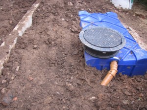
A ‘blue moon’ opportunity whilst we have the, one and only, chance to ever get a digger into this part of the site, so we invest in, well, a blue water tank. This will connect the rainwater discharge from the rear roof slope and the rear extension roof. It is a 1500 litre tank, about the size of 8 standard water butts – not huge, but as big as we can get into the space without major civil works and it will serve only to water the garden. The tank is a shallow dig unit from RainWater Harvesting. The photo shows the tank part-connected – with just the overflow connected to the underground surface water drain.
Category Archives: Extension
week 7: giant lintels arrive
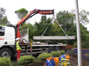
The ground bearing lintels arrive: these will sit on top of the concrete pipes. They are huge: 290 x 100mm and 3.5m long, and incredibly heavy. Having perhaps sounded a little smug about the amount of concrete saved (in the previous post), I don’t think we will have saved much financially. These lintels are specials and have cost a small fortune!
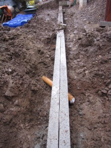
The photo above shows the lintels in place. Two 100mm wide lintels are placed side-by-side, allowing the 200mm aerated concrete blocks to be built straight off the lintels. Hopefully we’ll be out of the ground soon.
week 7: foundings cast
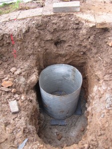
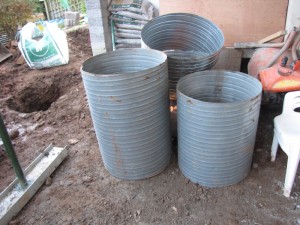
We bury a scandalous amount of concrete in this country to prop up our buildings. I was keen to ensure that our structural engineer came up with a ‘creative solution’ to mitigate the amount needed, as we have had to go so deep to ensure we are below the level of the sewer. The concrete ‘pipes’ seems a good solution and getting hold of the steel ducts was a good find by the contractor. The picture above shows one of the four ducts for the founding ‘moulds’ placed in-situ ready for the concrete pour. In total, we need 2.5m³ of concrete as opposed to 8.75m³ with a traditional deep trench fill, a saving of 70% of grey stuff.
week 6: underpinning and foundings
Yes, the rain came this week. 79mm fell here in 24 hours (Monday morning being the worst) – just perfect, absolutely perfect conditions to do anything other than dig the foundings for the new foundations! So, it has been slippy and sticky on site, which has meant slow progress. So not a huge amount to write about this week.
Not to despair, the guys have progressed as well as can be expected and have got the foundings prepared and ready for the first inspection by Building Control tomorrow (Friday). The concrete delivery is booked for the afternoon, immediately after the inspection sign off. So, all being well the foundations for the rear wall will be cast tomorrow. This is good as we’re expecting a dryish weekend before poor weather resumes next week.
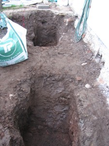
In an attempt to minimise the amount of concrete in our extra deep (1.2m) foundations (see earlier posts related to Wessex Water requirements), the design adopted uses 750 dia concrete pipes as opposed to a massive trench fill to this depth. The top photo of this entry shows 2 of the 4 foundings for these pipes. On top of these pipes will sit large lintels which we will build the walls off. Our contractor has sourced some off-cuts of 750dia ventilation ducts (photo below) which will be perfect for casting the foundations.
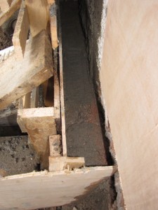
In the meantime, the underpinning has continued this week and the rear wall is now fully underpinned. This has gone well, but there’s more to be done as we work our way up the slope of the house. The photo below shows the, recently poured, underpinning section with the formwork and bracing (granted not the most interesting picture, but I am a bit short of visuals this week!).
week 5: underpinning starts
After the slab is removed and the earth excavated to the right level, the underpinning of the walls can commence. The photo above shows the first corner section of underpinning complete. Each section is approximately 1200mm long and is cast in alternate sequences. The photo shows the form-work for the second section being removed, the third and fourth sections (either side of the second) can be cast in one sequence, as per the structural engineer’s details.
The underpinning will continue along the internal side wall (behind the column in the photo) and progressively along the external side wall (far right in photo) in tandem with the excavation along the wall. Let’s hope for good weather!
week 5: out comes the lower ground floor
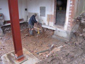
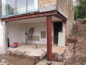
The picture shows the extent of the steel work now that the scaffolding has been removed. Toward the base of the new steel column, you can just make out the thermal break. The new insulated floor level is approximately 30mm above this break, and so the existing needs to come out.
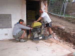
Concerned that a breaker drill will cause too much vibration (and noise), it is decided that a concrete saw would be best. This will cut the slab into chunks of manageable size for the digger to ‘scoop out’.
The photo above shows the saw in use. It takes best part of the day to cut the slab, but it is a success and the slab is removed. Beneath the slab is solid, rocky, undisturbed ground. The digger scoops out around 650mm of earth beneath the slab. This reveals the base of the back and side walls, ready for the under pinning. See next update
week 4: safely aground
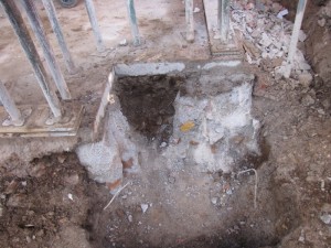
Well, first of all the base for the column needs to be prepared. Digging down around 1 metre below the existing ground slab and cutting through the existing and substantial foundations.
This new base will take the load of the whole corner of the house and needs to be pretty substantial. Our structural engineer specifies a depth of 400mm, but we decide to take it deeper to almost 600mm to get below the level of the existing foundations.
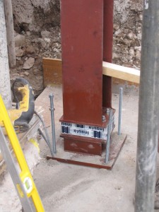
And so once the base is cast, the new post arrive s(late again!). The picture above shows it sitting on the new concrete base, which has been drilled and injected with the chemical resin anchor (as used for the horizontal steels).
The picture also shows the thermal break used in the column. This reduces the thermal conductivity in the column by a factor of 1500 compared to having no thermal break. The steel column has a thermal conductivity of 54 W/m.k, whereas the break has a conductivity of 0.035 W/m.k, This is a critical element for limiting the thermal bridging through the structure. It is still a compromise: ideally we wouldn’t be penetrating the thermal envelope with structural elements, but where this is necessary, so are these thermal de-couplers.
Finally, the column base is shuttered and then grouted with structural grout (as shown in the photo above). It will be bolted on Monday and the Acros will be struck. A project milestone and time for a quick glass of bubbly stuff before the guys go home for the weekend. They’ve done me proud, and I can relax a little having some proper structure beneath us again!
week 4: horizontal steels go in
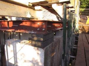
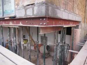
Whilst the house is temporarily supported, the horizontal steels arrive late, but the guys hang back to get the first section installed. The main span across the rear of the property goes in the next day. It takes three of us just to move the 200kg length, which is eventually teased into place and bolted to the shorter steel on the side wall as shown in the photo.
Using Hilti chemical anchor fixings, the web of the steel is fixed to the side of the slab along both steel sections as shown by the bolts sticking through the web (yet to be cut back).
Next, the concrete pad for the column needs to be prepared.
The masonry above the steel is reinstated using block work, allowing the Strongboys down the side of the house to be removed. The Acros beneath the slab are rearranged, one-by one to support the newly installed steels – the weight of the slab now being transferred to the new steels. This allows the corner section of the existing wall to be demolished and the ground slab to be removed as will be shown in the next update…
week 2: structural alterations
In meeting the structural engineer, it was agreed that the lower ground slab should stay for the time being as it will be easier to temporarily prop the upper slab from this. In the meantime we have been deciding the best approach for the main structural alterations and the insertion of the steels.
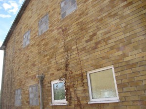
First of, five of the seven side windows have been in-filled, the remaining two will come out later. In-filling the windows will strengthen the wall prior to the demolition of the lower section of this wall.
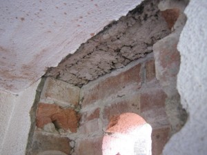
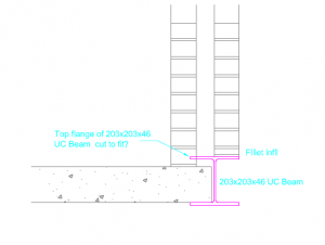
Exposing the slab edge reveals that it is supported entirely by the inner brick leaf. This makes the sequencing simpler as the slab can be supported as proposed, with an array of Acro supports below. The outer brick leaf will need supporting independently, but there is not as much load to contend with as we thought. As the sketch detail above right shows, we have a slight clash with the proposed steel now and we will need to trim the top flange such that it doesn’t foul the inner brick leaf. Our structural engineer is okay with this providing we bolt the web of the steel to the edge of the concrete slab.
getting there with the tender
Having had a few meetings and pricing addendums with our preferred contractor, we are now getting nearer to the project budget. Essentially, we have re-scoped the works so that the contractor will do the extension, but not the fit-out, e.g. kitchen. For the existing house they will do all necessary external works including:
- External wall insulation
- Replacement windows
- Grinding off concrete gutters and replacing all rainwater goods
- Structural works and interfacing with extension

