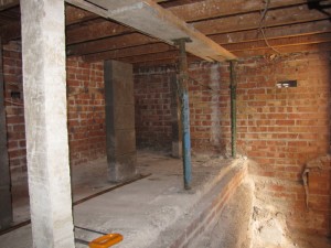
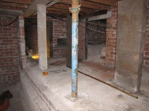
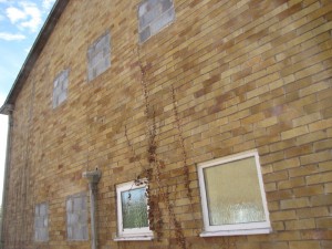
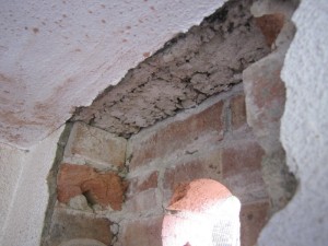
There is a vast void beneath the house, thanks to the slope that the house is built on. In its present state, it cannot be effectively used due to the amount of structural walls and supports. Some of these are now being demolished and replaced with lintels on block piers. The photo above shows the block piers constructed on top of the existing retaining wall. Elsewhere, access hatches are being cut into the walls as can be seen in the photo below.
Opening up under the house in this way allows the space to be used more effectively. The part of the void in the photos (with the greatest headroom) will be part of the heated volume of the house and will become a plant room for the hot water cylinder and an archive/storage area to house items currently in the loft. The loft will be almost unusable for storage due to the amount of insulation proposed and its low (22°) pitch.
The void will also enable good access for installing the new services: pipes, cables, ducts, and will be excellent for getting the floor insulation into the unheated part of the void toward the front of the house where it becomes more of a crawl space. The drawing extract below shows the extent of the void and the delineation between heated and unheated areas (insulation and air barrier line shown in green).

